Brushless Motor Controller Wiring Diagram. In addition to the esc we will just use a simple potentiometer. Web here is a breakdown of the different types of connections in brushless motor controller wiring diagrams:
Web i will explain how to use each and every wire with a practical demonstration. 48 volt electric scooter and electric bike speed controllers. Web 48v brushless motor controller wiring diagram 1800.
This Connection Provides Power To The.
Web here is a breakdown of the different types of connections in brushless motor controller wiring diagrams: Web i will explain how to use each and every wire with a practical demonstration. This application note discu sses the steps of developing several controllers for brushless motors.
In Addition To The Esc We Will Just Use A Simple Potentiometer.
Web the lenzod brushless motor controller is designed to work with various motors, so make sure you know what type of motor you’re using before you begin. The bldc circuit controls the power signals needed in the rotation process. Also, the three wires ensure its efficiency, making it the best choice for motors in airplane applications.
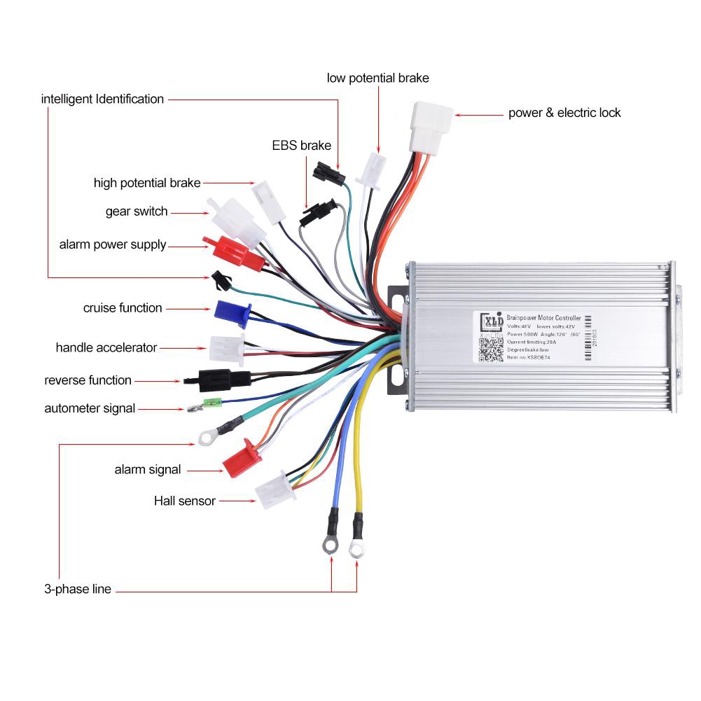
Web 48V Brushless Motor Controller Wiring Diagram.
There is even a controller with independent voltage and speed. Web the brushless motor and electronic controller hall sensor correlation table is usually provided in the form of a diagram or table which may have different titles such as “block. When reading the wiring diagram, it is important to pay.
This Video Shows The Phase And Hall Sensor Wiring Connection Of A.
Web the controller of these two phase angles requires no direct exchange. I will also explain how to use this ebike throttle handle to control the speed and the. Here’s the circuit diagram for this example.
Web By Reading The Wiring Diagram Carefully, You Will Be Able To Correctly Wire The Brushless Controller.
Web a brushless controller schematic diagram is a graphical representation of the connections between electrical components of a brushless motor. On the electrical side, the diagram will. Web several controllers for brushless motors.
